
Why the Water Circuit Is Designed as a Closed Loop
In a water-injected oil-free screw compressor, water serves as the compression medium — simultaneously cooling, sealing, and lubricating inside the compression element. Unlike an open system where water would be injected once and discharged with the compressed air, the water circuit in a properly designed machine is closed loop: the same treated water is separated from the compressed air, cooled, filtered, and re-injected continuously. This closed-loop design is not a minor convenience feature — it is the engineering solution to three interconnected problems. First, using a closed loop allows the water quality to be controlled precisely, because the circuit is not continuously refreshed with uncontrolled incoming supply water. Second, it dramatically reduces water consumption — instead of consuming fresh RO-treated water continuously, the machine only needs makeup water to replace the small quantities lost through evaporation into the compressed air and minor condensate drainage. Third, it keeps water temperature stable throughout the operating cycle, allowing the heat exchanger to be sized precisely for the closed-loop heat load rather than for variable supply water conditions.
The Complete Water Circuit: Component by Component
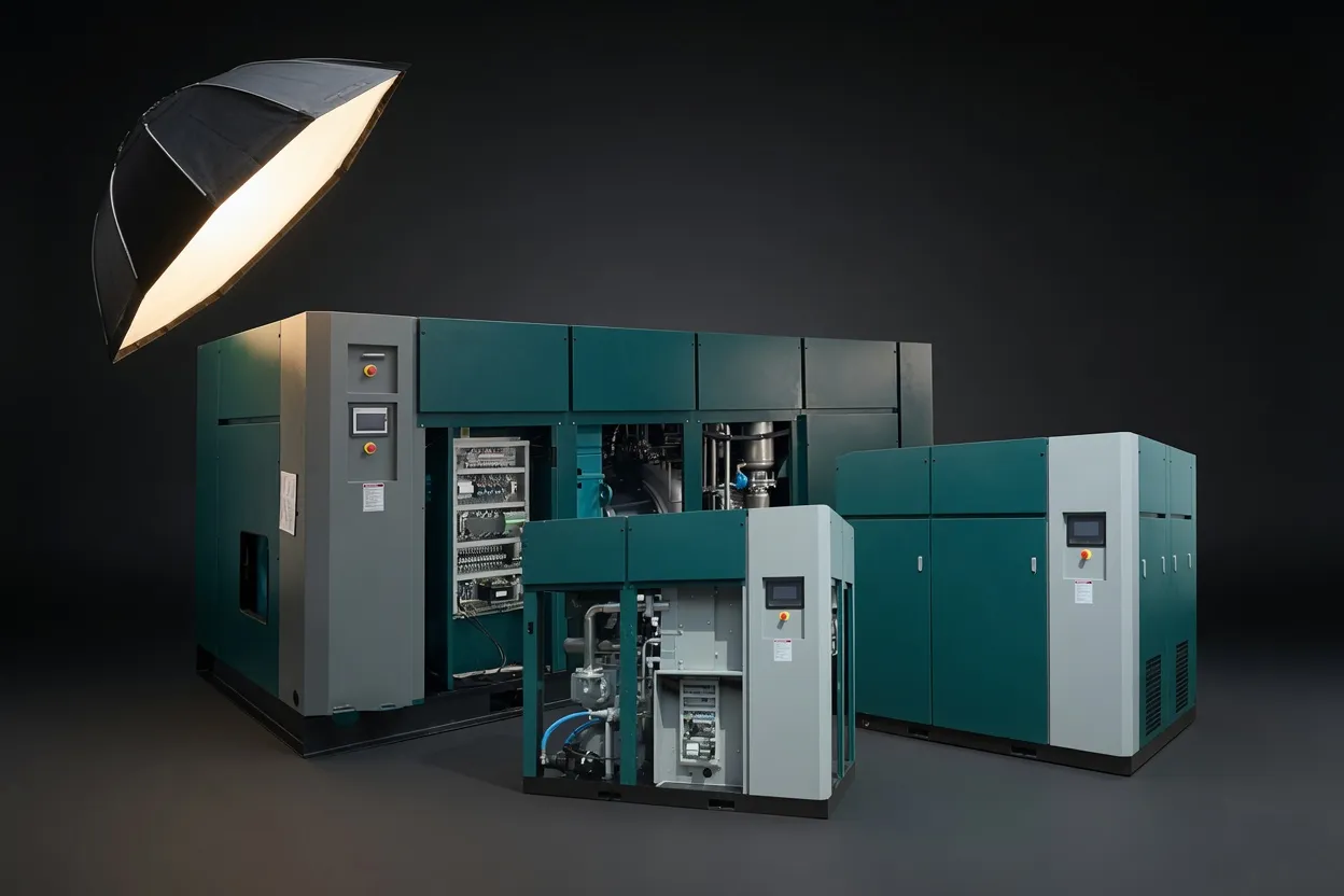
A complete closed-loop water circuit typically includes seven functional elements. Each has a specific role in maintaining water quality and circuit performance across thousands of operating hours.
How the Water Circuit Handles Heat Across the Full Load Range
The heat load the water circuit must handle varies with compressor load. At full load, compression heat generation is at its maximum, and the circuit must transfer this heat through the water cooler as fast as it is produced. On a VSD machine at part load, compression heat generation falls proportionally, and the heat exchanger capacity becomes more than adequate — circuit water temperature stays lower, which actually improves the near-isothermal behaviour of the compression process at part load. This self-regulating behaviour is one reason why variable speed water-injected screw compressors maintain good thermodynamic efficiency across their full speed range, rather than showing efficiency degradation at part load as some fixed-speed machines do when they partially unload.
The water cooler must be sized for maximum continuous load at the highest expected ambient temperature — not just at rated conditions. A cooler undersized for peak summer ambient temperatures will allow circuit water temperature to rise above design, reducing heat absorption per kilogram of injected water and increasing discharge temperature toward levels that stress rotor coatings and shaft seals. Proper thermal sizing of the water cooler, including a safety margin for ambient temperature variation, is a critical design detail that distinguishes well-engineered packages from those optimised purely for impressive specification sheet numbers.
| Circuit Parameter | Typical Range | Alarm Threshold | Shutdown Threshold |
|---|---|---|---|
| Injection water temperature | 25–45°C | 55°C | 65°C |
| Discharge temperature | 60–80°C | 85°C | 95°C |
| Circuit water conductivity | <50 µS/cm | 100 µS/cm | 200 µS/cm |
| Circuit water pH | 6.5–8.0 | <6.0 or >9.0 | <5.5 |
| Water filter differential pressure | <0.5 bar | 0.8 bar | 1.2 bar |
Reference values. Always follow the specific manufacturer’s alarm and shutdown setpoints for the installed machine model.
Circuit Flush and Water Change: Why and How Often
Even with RO makeup water, the circuit water gradually accumulates dissolved CO₂ from the inlet air stream (forming carbonic acid), trace contaminants from the air, and micro-quantities of material shed by filter elements and circuit components. Over time, conductivity and pH drift toward levels that increase corrosion risk on stainless water circuit components and reduce rotor coating integrity. A periodic circuit flush — draining the circuit completely, flushing with fresh RO water, and refilling — resets water quality to the starting baseline. Most manufacturers specify this at 4,000–6,000 operating hour intervals, though actual frequency should be guided by the inline monitoring data rather than fixed calendar-based scheduling. For a detailed service framework, refer to the complete routine maintenance checklist for water-lubricated oil-free air compressors which covers each circuit service task in sequence.
Frequently Asked Questions
Get the Full Water Circuit Design for Your Application
Hangzhou Ever Power provides complete water circuit schematics, commissioning procedures, and water quality management protocols with every compressor order.
Hangzhou Ever Power Air Compressor Co., Ltd. · Shenhua Road, Hangzhou 310031 · +86 13083988828